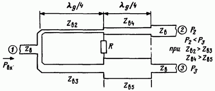
Impedance of Wilkinson microstrip divider
The Wilkinson divider is a device designed to divide the power of a microwave signal into two output ports. Different sections of the divider consist of a microstrip line of different widths. There are four such sections in total and each has its own impedance.

- first_impedance
electrical_impedanceof the first section.
- Symbol:
Z_1- Latex:
\(Z_{1}\)
- Dimension:
impedance
- second_impedance
electrical_impedanceof the second section.
- Symbol:
Z_2- Latex:
\(Z_{2}\)
- Dimension:
impedance
- third_impedance
electrical_impedanceof the third section.
- Symbol:
Z_3- Latex:
\(Z_{3}\)
- Dimension:
impedance
- fourth_impedance
electrical_impedanceof the fourth section.
- Symbol:
Z_4- Latex:
\(Z_{4}\)
- Dimension:
impedance
- transmission_line_impedance
electrical_impedanceof the transmission line to which the divider is connected.
- Symbol:
Z_0- Latex:
\(Z_{0}\)
- Dimension:
impedance
- Symbol:
k- Latex:
\(k\)
- Dimension:
dimensionless
- law
[Z_1, Z_2, Z_3, Z_4] = [Z_0 * sqrt(k * (1 + k^2)), Z_0 * sqrt((1 + k^2) / k^3), Z_0 * sqrt(k), Z_0 / sqrt(k)]- Latex:
- \[\begin{split}\begin{pmatrix} Z_{1} \\ Z_{2} \\ Z_{3} \\ Z_{4} \end{pmatrix} = \begin{pmatrix} Z_{0} \sqrt{k \left(1 + k^{2}\right)} \\ Z_{0} \sqrt{\frac{1 + k^{2}}{k^{3}}} \\ Z_{0} \sqrt{k} \\ \frac{Z_{0}}{\sqrt{k}} \end{pmatrix}\end{split}\]